

Welcome again to a different Python tutorial for the Raspberry Pi 4! The earlier tutorial confirmed us the best way to assemble a Raspberry Pi-powered mobile phone with a microphone and speaker for making and receiving calls and studying textual content messages (SMS). To make our Raspberry Pi 4 into a completely practical smartphone, we constructed software program in Python. As we monitored textual content and cellphone calls being despatched and obtained between the raspberry pi and our cell phone, we skilled no technical difficulties. However on this tutorial, you may discover ways to hook up the PCF8591 ADC/DAC module to a Raspberry Pi 4.
Since most sensors solely output their knowledge in analog values, changing them to binary values {that a} microcontroller can perceive is a vital a part of any built-in electronics challenge. A microcontroller’s capacity to course of analog knowledge necessitates utilizing an analog-to-digital converter.
Some microcontrollers, together with the Arduino, MSP430, and PIC16F877A, comprise an onboard analog-to-digital converter (ADC), whereas others, just like the 8051 and Raspberry Pi, don’t.
Required Elements
Raspberry-pi 4
PCF8591 ADC Module
100K Pot
Jumper wires
You might be anticipated to have a Raspberry Pi 4 with the newest model of Raspbian OS put in on it, and that you’re aware of utilizing a terminal program like putty to hook up with the Pi through the Web and entry its file system remotely. These unfamiliar with Raspberry Pi can study the fundamentals by studying the articles beneath.
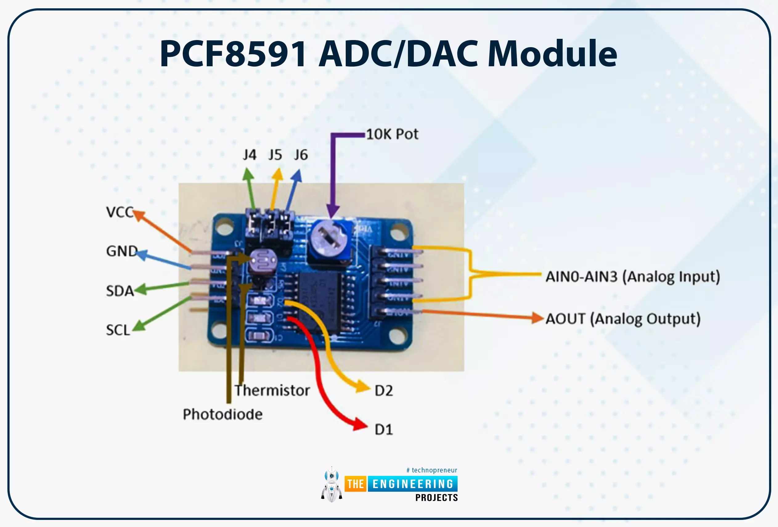
PCF8591 ADC/DAC Module
Every of the ten pins on the PCF8591 module could learn analog values as excessive as 256 on the PCF8591’s digital facet or vice versa. The board has a thermistor and LDR circuit. Enter and output from this module are each analogs. To facilitate the I2C protocol, it has a devoted serial clock and serial knowledge deal with pins. The availability voltage ranges from 2.5 to 6V, and the stand-by present is minimal. We are able to additional flip the module’s potentiometer knob to regulate the enter voltage. A complete of three jumpers may be discovered on the board. Switching between the thermistor, LDR/photoresistor, and adjustable voltage entry circuits is feasible by connecting J4, J5, and J6. D1 and D2 are two LEDs on the board, with D1 displaying the energy of the output voltage and D2 indicating the ability of the availability voltage. When the availability or output voltage is elevated, the brightness of LEDs D1 and D2 are correspondingly enhanced. Potentiometers related to the LEDs’ VCC or AOUT pins additionally permit testing.
Microprocessors, Arduinos, Raspberry Pis, and different digital logic circuits can work together with the bodily surroundings because of Analogue-to-Digital Converters (ADCs). Many digital techniques collect details about their settings by analyzing the analog indicators produced by transducers resembling microphones, mild detectors, thermometers, and accelerometers. These indicators continually range in worth since they’re derived from the bodily world.
Digital circuits use binary indicators, which may solely be in considered one of two states, “1” (HIGH) or “0” (LOW), versus the infinitely variable voltage values supplied by analog indicators (LOW). Subsequently, Analogue-to-Digital Converters (A/D) is a vital digital circuit for translating between continually various analog impulses and discrete digital indicators.
To place it merely, an analog-to-digital converter (ADC) is a tool that, given a single instantaneous studying of an analog voltage, generates a singular digital output code that stands in for that studying. The precision of an A/D converter determines what number of binary digits, or bits, are utilized to signify the unique analog voltage worth.
Analogue and Digital Indicators
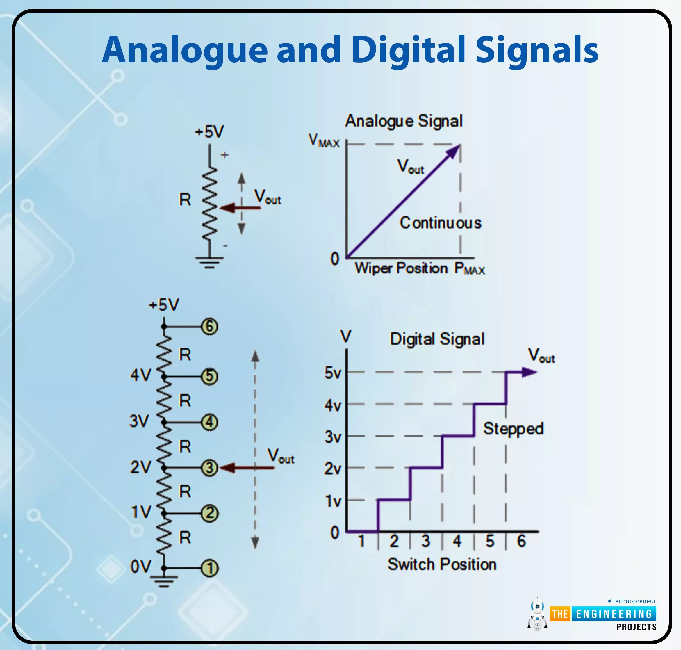
By rotating the potentiometer’s wiper terminal between 0 and VMAX, we might even see a steady output sign with an limitless set of output values associated to the wiper place. In a potentiometer, the output voltage continually varies whereas the wiper is moved between fastened positions. Variations in temperature, stress, liquid ranges, and brightness are all examples of analog indicators.
A digital circuit makes use of a single rotary change to regulate the potential divider community, taking the place of the potentiometer’s wiper at every node. The output voltage, VOUT, quickly transitions from one node to the following because the change is turned, with every node’s worth representing a a number of of 1.0 volts.
The output is assured at 2-volt, 3-volt, 5 volts, and so on., however NOT a 2.5-volt, 3.1-volt, or 4.6-volt output. Utilizing a multi-position change and extra resistive elements within the voltage-divider community, leading to extra discrete switching steps, would permit for producing finer output voltage ranges.
By this definition, we are able to see {that a} digital sign has discrete (step-by-step) values, whereas an analog sign’s values change constantly over time. We’re going from “LOW” to “HIGH” or “HIGH” to “LOW.”
So the query turns into the best way to remodel an infinitely variable sign into one with discrete values or steps {that a} digital circuit can work with.
Changing from Analog to Digital
Though a number of commercially obtainable analog-to-digital converter (ADC) chips exist, such because the ADC08xx household, for changing analog voltage indicators to their digital equivalents, a major ADC may be constructed out of discrete elements.
Utilizing comparators to detect numerous voltage ranges and output their switching sign state to an encoder is a simple technique often known as parallel encoding, flash encoding, simultaneous encoding, or a number of comparator converters.
The equivalence output script for a given n-bit decision is fashioned by a sequence community of accuracy resistors and a sequence of comparators which might be related however equally spaced.
As quickly as an analog sign is supplied to the comparator enter, it’s evaluated with a reference voltage, making parallel converters advantageous due to their ease of development and lack of want for timing clocks. The next comparator circuit could also be of curiosity.
A Logic Comparator
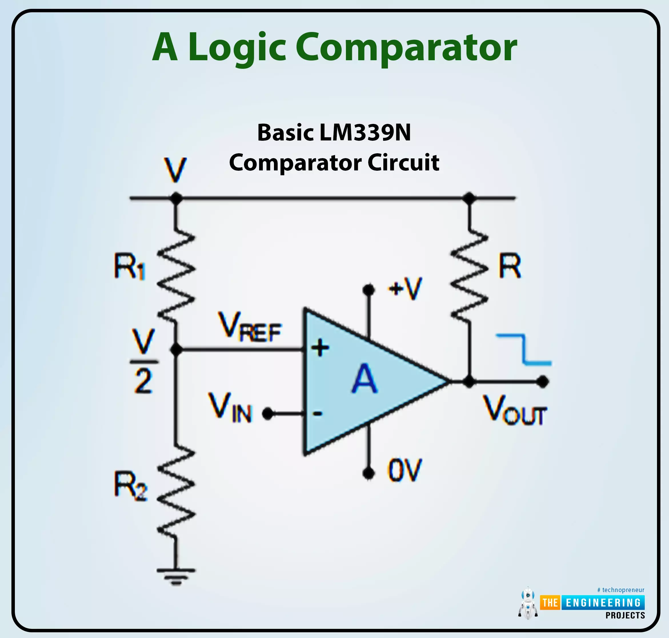
The LM339N is an analog comparator that compares the relative magnitudes of two voltage ranges through its two analog inputs (one constructive and one adverse).
The comparator receives two indicators, one representing the enter voltage (VIN) and the opposite representing the reference worth (VREF). The comparator’s digital circuits state, “1” or “0,” is decided by evaluating two output voltages on the enter of the comparator.
One enter (VREF) receives a reference voltage, and the opposite enter (VIN) receives the enter voltage to be in comparison with it. Output is “OFF” by an LM339 comparator when the enter energy is decrease than (VIN VREF) and “ON” when the enter energy is greater than the usual voltage (VIN > VREF). A comparator is a tool to find out which of two voltages is bigger.
Utilizing the potential divider community established by R1 and R2, we are able to calculate VREF. If the 2 resistors are similar in worth (R1 = R2), then the reference voltage might be half the enter energy (V/2). Subsequently, like with a 1-bit ADC, the output of an open-collector comparator is HIGH if VIN is decrease than V/2 and LOW in any other case.
Nevertheless, by rising the variety of resistors within the voltage divider circuit, we are able to “divide” the voltage supply by an quantity equal to the ratio of the resistors’ resistances. Nevertheless, the variety of comparators wanted will increase with the variety of resistors within the voltage-divider community.
For an “n”-bit binary output, the place “n” is often between 8 and 16 bits, a 2n- 1 comparator can be wanted on the whole. As we noticed beforehand, the comparator utilized by the one-bit ADC to find out whether or not or not VIN was extra important than the V/2 voltage output was 21 minus 1, which equals 1.
If we need to construct a 2-bit ADC, we’ll want 22-1 or “3” comparators for the reason that 4-to-2-bit encoder circuitry depicted above requires 4 distinct voltage ranges to signify the 4 digital values.
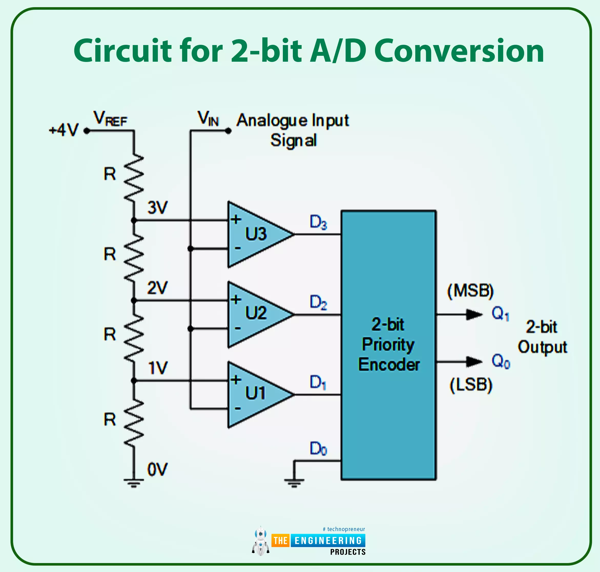
Circuit for 2-bit A/D Conversion
For every of the 4 potential values of the analog enter of:
A/D Conversion Output, 2-Bit
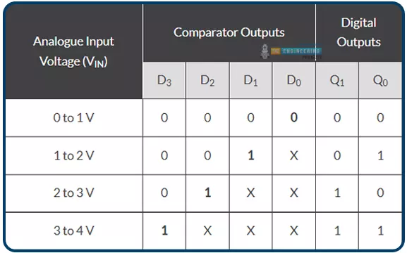
The place X is a “do not care” assertion, representing a logical 0 or 1.
Clarify how this analog-to-digital system operates. An analog-to-digital converter (A/D) should generate a trustworthy digital copy of the Analog enter sign to be of any worth. To maintain issues simple, we have assumed that VIN is someplace between 0 and 4 volts and have adjusted VREF and the voltage divider community so that there’s a 1 V drop between every resistor on this easy 2-bit Analog – to – digital instance.
A binary zero (00) is output by the encoder on pins Q0 and Q1 when the enter voltage, VIN, is lower than the reference voltage degree, which happens when VIN is between 0 and 1 volts (1V). Since comparator U1’s reference voltage enter is about to 1 volt, when VIN rises above 1 volt however is beneath 2 volts, U1’s HIGH output is triggered. When the enter modifications at D1, the precedence encoder, used for the 4-to-2-bit encoding, generates a binary results of “1.” (01).
Do not forget that the inputs of a Precedence Encoder, just like the TTL 74LS148, are all assigned completely different precedence ranges. The best precedence enter is at all times used because the output of the precedence encoder. So, when the next precedence enter is out there, lesser precedence inputs are disregarded. Subsequently, if there are lots of inputs concurrently at logic state “1”, solely the enter with excessive precedence could have its output code mirrored on D0 and D1.
Thus, now that VIN is bigger than 2 volts—the following reference voltage degree—comparator U2 will sense the distinction and output HIGH. Nevertheless, when VIN is greater than 3 volts, the precedence encoder will output a binary “3” (11), as enter D2 has a excessive precedence than inputs D0 and D1. Every comparator outputs a HIGH or LOW state to the encoder, producing 2-bit binary knowledge between 00 and 11 as VIN decreases or modifications between each reference voltage degree.
That is nice and all, however commercially obtainable precedence encoders, just like the TTL, are 8-bit circuits, and if we use considered one of these, six of the binary numbers will go unused. A digital Ex-OR gate and a grid of signaling diodes can create an easy encoder circuit.
Diode-based 2-bit ADC

Earlier than feeding the diodes, the outcomes of the comparators undergo an Unique-OR gate to be encoded. Every time the diode is reverse biased, an exterior pull-down resistor is related between the diodes’ outputs and floor (0V) to take care of a LOW state and forestall the outputs from floating.
Additionally, as with the primary board, the worth of VIN controls which comparator sends a HIGH (or LOW) sign to the exclusive-OR gates, which offer a HIGH output if both of the inputs is HIGH however not each (the corresponding Boolean is Q = A.B + A.B). The AND-OR-NAND gates of combinational logic is also used to construct these Ex-OR gates.
The problem with each of those 4-to-2 converter designs is that the enter analog voltage at VIN must range by one full volt for the encoder to range its output code, limiting the precision of the easy two-bit A/D converter to 1 volt. The output decision may be improved by using extra comparators to transform to a three-bit A/D converter.
D/A Converter, 3-Bit
The aforementioned parallel ADC takes a voltage studying between 0 and over 3 volts as an analog enter and turns it right into a binary code with solely 2 bits. Since there are 23 = 8 attainable digital outputs from a 3-bit digital circuits system, the enter analog voltage may be in comparison with a scale of eight voltages, every of which is one-eighth (1/8) of the voltage provide. Which means we are able to now measure to an accuracy of 0.5 (4/8) volts and that 23-1 comparators are wanted to generate a binary code with a 3-bit decision (from 000 (0) to 111 (7)).
Circuit for 3-bit Analog-to-Digital Conversion

It will present us with a three-bit code for every of the eight potential values of the analog enter of:
The results of a Three-Bit Analog-to-Digital Converter
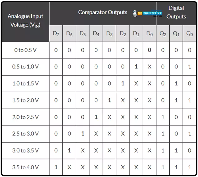
An “X” could also be a logic 0 or a logic 1 to point a “do not care” state.
Then we are able to see that extra comparators and energy ranges are required and extra output binary bits when the ADC’s decision is elevated.
Subsequently, an analog-to-digital converter with a 4-bit decision wants solely 15 (24-1) comparators. An eight-bit decision requires 255 (28-1) comparators. A ten-bit decision wants 1023 comparators, and so on. Subsequently, the complexity of one of these Analog-to-Digital Converter circuit will increase because the variety of output bits will increase.
Provided that just a few binary bits are wanted to make a learn on a show unit to signify the reference voltage of an enter analog sign can a parallel or flashed A/D converter rapidly be developed as a part of a challenge because of its quick real-time conversion price.
As an enter interface circuit element, an analog sign from sensors or transducers is transformed right into a digital binary code by an analog-to-digital converter. Equally, a digital binary code may be transformed right into a comparable analog amount utilizing a Digital-to-Analog Conversion for output interfacing to function a motor or actuator or, extra typically, in audio functions.
Raspberry Pi’s I2C pins
Realizing the Raspberry Pi’s I2C port pins and establishing the I2C connection within the pi 4 are the preliminary steps in utilizing a PCF8591 with the Pi.
GPIO2 and GPIO3 on the Rpi Mannequin are utilized for I2C communication on this information.
Raspberry Pi I2C Configuration
Raspberry Pi lacks I2C help by default. Subsequently, it should be activated earlier than the rest. Activate Raspberry Pi’s I2C port.
First, open a terminal and enter sudo raspi-config.
The RPi 4 Software program Configuration Instrument has opened.
Third, activate the I2C by deciding on Interfacing choices.
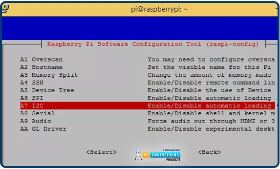
Restart the Pi after enabling I2C.
Studying the PCF8591’s I2C Deal with with a Raspberry Pi
The Raspberry Pi has to know the I2C deal with of the PCF8591 IC earlier than communication can start. It’s possible you’ll get the deal with by linking the PCF8591’s SDA and SCL pins to the Raspberry Pi’s personal SDA and SCL jacks. The 5-volts and GND pins needs to be related as effectively.
It’s possible you’ll discover the deal with of an connected I2C system by opening a terminal and getting into the next command.
sudo i2cdetect –y 1 or sudo i2cdetect –y 0
After finding the I2C deal with, the following step is establishing the circuit and establishing the required libraries to make use of PCF8591 and a Raspberry Pi 4.
Connecting the PCF8591 ADC/DAC Module to the Raspberry Pi 4
The circuit diagram to interface the PCF8591 with the Raspberry Pi is easy. On this instance of interfacing, we’ll learn the analog sign from any analog inputs and show them within the Raspberry Pi terminal. We’ve a 100K pot to regulate the settings.
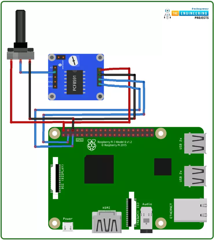
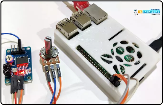
Pi’s GPIO2 and GPIO should be related to the ability provide and floor. Then, hook up GPIO3 and GPIO5 to SDA and SCL, respectively. Final however not least, hyperlink AIN0 to a 100K pot. As an alternative of utilizing the Terminal to view the ADC values, a 16×2 LCD may be added.
The A/D Conversion Python Program
The whole code and demo video are included after this information.
To speak with the I2C bus, you have to first import the SMBus library after which use the time library to specify how lengthy to attend earlier than outputting the worth.

import smbus
import time
Create some variables now. The I2C bus deal with is saved within the first variable, and the primary analog enter pin’s deal with is saved within the second variable.
deal with = 0x48
A0 = 0x40
Subsequent, we have invoked the library smbus’s SMBus(1) perform to create an object.

bus = smbus.SMBus(1)
The primary line within the whereas instructs IC to take a studying from the primary analog sign pin. Deal with info learn from an Analog pin is saved as a numeric variable within the second line. Exit with the worth printed.

Whereas True:
bus.write_byte(deal with,A0)
worth = bus.read_byte(deal with)
print(worth)
time.sleep(0.1)
Lastly, put the Python script in a file ending in.py and run it within the Raspberry Pi terminal with the command beneath.

python filename.py
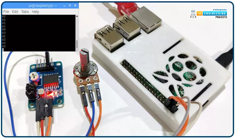
Be certain that the I2C communication is turned on and that the pins are linked in response to the diagram earlier than operating the code, or else you’ll get errors. It is time for the analog readings to look within the terminal format beneath. The values progressively shift as you flip the pot’s knob. Discover out extra about getting the software program to work in
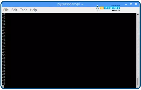
Right here is the total Python script.
import smbus
import time
deal with = 0x48
bus = smbus.SMBus(1)
whereas True:
bus.write_byte(deal with,A0)
worth = bus.read_byte(deal with)
print(worth)
time.sleep(0.1)
ADC’s Sensible Makes use of
We rely closely on digital devices in as we speak’s high-tech society. The digital sign is the driving drive behind these digital units. Whereas most numbers are represented digitally, few nonetheless use analog notation. Thus, an ADC is employed to rework analog impulses into digital ones. ADC can be utilized in an infinite number of contexts. Listed below are just a few examples of their use:
The digitized voice sign is utilized by cell telephones. The voice is first reworked to digital kind utilizing an ADC earlier than being despatched to the mobile phone’s transmitter.
Digital photographs and flicks shot with a digital camera may be considered on any laptop or cell system because of an analog-to-digital converter.
X-rays and MRIs are simply two examples of medical imaging methods that use ADC to go from Analog to digital earlier than additional processing. Then, they’re adjusted so that everybody can comply with alongside.
ADC converters can even switch music from a cassette tape to a digital format, resembling a CD or a USB flash drive.
The Analog-to-Digital Converter (ADC) in a digital oscilloscope converts analog indicators to digital ones that may then be displayed and used for different causes.
The air conditioner’s built-in temperature sensors permit for constant consolation ranges. The onboard controller reads the temperature and makes changes primarily based on the info it receives from the ADC.
These days, virtually all the pieces has a digital counterpart, so each gadget should additionally embody an ADC. For the easy cause that its operations require a digital area accessible solely through an analog-to-digital converter (ADC).
Conclusion
This piece taught us the best way to join a Raspberry Pi 4 to a PCF8591 Analogue – to – digital decoder module. We’ve noticed the output being proven as integers on our Terminal. We’ve additionally researched how the ADC generates its output indicators. Right here we are going to use OpenCV and a Raspberry Pi 4 to create a social distance detector.


0 Comments